
Resistor Voltage = Supply Voltage - LED Turn On Voltage (Vf)

This current is the same amount that flows to the LED but the voltage across the resistor is different because the LED has a turn on voltage which you subtract from the supply voltage: The way to decide how much resistance you need, you need to use Ohm’s law for the current through the resistor.

when positive of ohmmeter is connected to anode of diode then ohmeter measures low resistance. A red LED uses the least amount of voltage to turn on, about 1.8 v while some blue LEDs need more than 3.0 v. Diode will have very high resistance as seen from Cathode to Anode so when ohmmeter is used, first its polarities should be known.because positive of ohmeter supplies positive voltage. To choose the right amount of resistance for the LED, you also need to know what its turn on voltage (Vf) is. This is usually about 20 milliamps for most single color LEDs. An anode is an electrode of a device through which conventional current (positive charge) flows into the device from an external circuit, while a cathode is an electrode through which conventional current flows out of the device. The amount of resistance needed depends on how much current the LED will use to be bright enough to see but not so much that it burns itself out. To make sure that the LED isn’t damaged by too much current, the connection between it and the voltage supply needs a resistor. If the supply voltage you’re using is more than then turn on voltage, you need a resistor between one of the LED leads and the connection to either GND or the supply voltage. The negative side is called the cathode.īecause diodes are made of semiconductor material, they have a very specific voltage where they will turn on. The voltage supply side of the diode is the positive (+) side, this is called the anode. All diodes exhibit avalanche behaviour in reverse a zener is simply defined for where reverse. A thyristor is a semiconductor device built from four alternating p- and n-doped layers. The Anode and cathode are defined by the dopants (group III for P and group V for N). Thyristor Function: A Switch-Controlled Diode. For an LED to work it needs to be connected to a voltage source with the correct side. A silicon diode (of any type) is basically just two doped regions of silicon (with the exception of PIN diodes which have an intrinsic region). This means that LEDs (and other diodes) have positive (+) and negative (-) sides to them. When the positive probe (usually red) is touching the anode and the negative probe (usually black) is touching the cathode the multimeter will show a resistance reading.LEDs are diodes which are elecronic devices that only allow current to go through them in one direction.

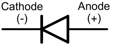
the circuit diagram symbol for an LED is shown below and the direction of flow is also indicated by the arrow. LEDs have an ultra-thin gold wire whisker bond to the anode so the heat sink is the cathode but since the wire bond is large in these diodes, they don’t have to look small which is why they conduct heat well to both terminals. Regular diodes are used in circuits with a forward bias applied, meaning that a positive voltage is placed across the diode, with current being driven from the anode (the ‘p-side’ of the junction), to the cathode (the ‘n-side’ of the junction). If the LED is connected in the wrong direction it will not illuminate and may damage the LED. The current flow can flow only from the ANODE (+) terminal to the CATHODE (-) terminal. It is very important that LEDs are connected to a circuit in the right direction. The positive pin is the ANODE (+) and the negative pin is the CATHODE (-). A device that blocks current in one direction while letting current flow in another direction is called a diode. LEDs are diodes and diodes only allow electrical current to flow in one direction, therefore LEDs are polarised.


 0 kommentar(er)
